Building a Server Room, Part 2: Fibre, Floor, and First Frames
This is the second in a series of five posts documenting the planning, architecture, and build of a new server room under various building and budgetary constraints.
- Part 1 — Nine Cabinets into Three
- Part 2 — Fibre, Floor, and First Frames
- Part 3 — Passive Infrastructure and the Carrier Handoff
- Part 4 — Power, Cooling, and Connectivity
- Part 5 — Live, Patched, and Moved In
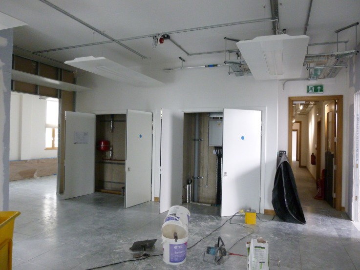
Five days on from part 1 (28 July 2014). The shell is ready, but before the racks can go in we need a carrier circuit, cable pathways, and somewhere to push the existing building services out of the way.
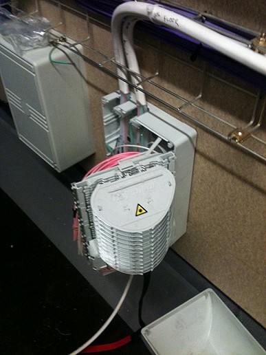
A BT OpenReach engineer is blowing fibre from the plant room splice point up to the comms room. The plant cupboard above sits between the building riser and our space, and the splice enclosure is where the carrier’s responsibility ends and ours begins.
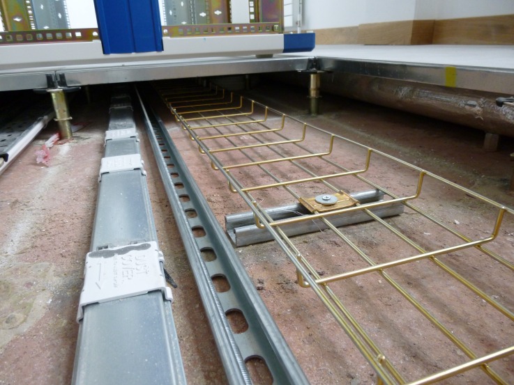
Inside the comms room, there isn’t much space under that raised floor. The original cable basket and ducting had to be removed and re-routed to make room for everything that actually needed to sit down there.
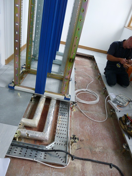
Those pipes are a problem, and the raised floor offers only 11cm of clearance. Every cable tray, busbar, and earth strap that has to sit under the floor is competing with pre-existing building services for a sliver of vertical room.
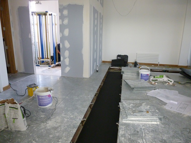
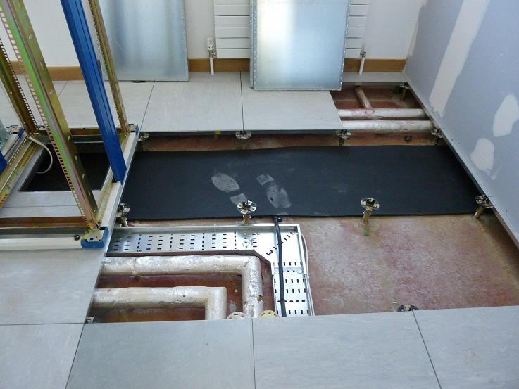
The matting traces the path the patch cables will take to reach the comms room. Setting it out now lets the cabling contractor pull the bulk runs without scuffing the freshly-laid floor tiles on the open-plan floor space.
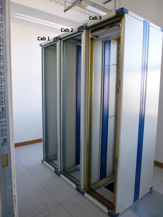
Cab 1 will be the patching and comms cabinet. Cab 2 and cab 3 will hold the development and infrastructure servers we’ve kept on-prem.
Part 1: ← Nine cabinets into three · Part 3: Passive infrastructure and the carrier handoff →