Building a Server Room, Part 4: Power, Cooling, and Connectivity
This is the fourth in a series of five posts documenting the planning, architecture, and build of a new server room under various building and budgetary constraints.
- Part 1 — Nine Cabinets into Three
- Part 2 — Fibre, Floor, and First Frames
- Part 3 — Passive Infrastructure and the Carrier Handoff
- Part 4 — Power, Cooling, and Connectivity
- Part 5 — Live, Patched, and Moved In
Four days on from part 3 (22 August 2014). Patch panels are in, the carrier is live, and the room now has to be given power, cooling, and the wireless coverage that the open-plan floor space runs on. Before any of that, a note on telephony: we’ve abandoned the traditional PBX and ISDN lines in favour of SIP trunking and VoIP handsets. One fewer system in the rack and one fewer copper service into the building.
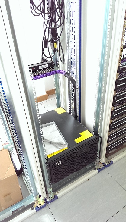
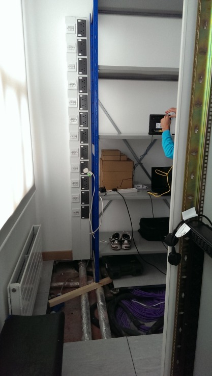
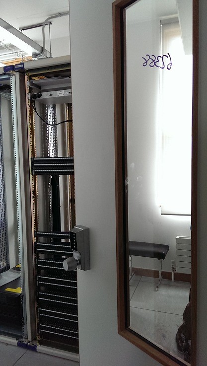
The UPS is installed at the base of the rack due to its weight. The three cabinets are bolted together as a single mechanical assembly, with the side panels left in place so that each cabinet keeps its own front-to-back airflow path rather than turning the row into one big shared thermal zone. I’d originally planned a different orientation to give the row a hot-and-cold-ish split, but the floor void left us no choice (the bloody pipes again, same story as the cab 1/cab 3 swap in part 3), so the racks went where they could physically sit. Three cabinets in a row against a wall don’t give you proper hot/cold aisles anyway, just sensible per-cabinet containment.
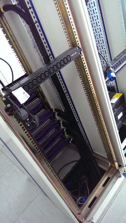
Patch panels, power lines, UPS, and PSUs are installed and the cabinets are earthed. Power into each rack arrives via IP44 quick-release angled commando sockets under the raised floor: 16A single phase to cab 3, and a mix of 16A and 32A feeds to cabinets one and two, sized for what each cabinet is expected to hold.
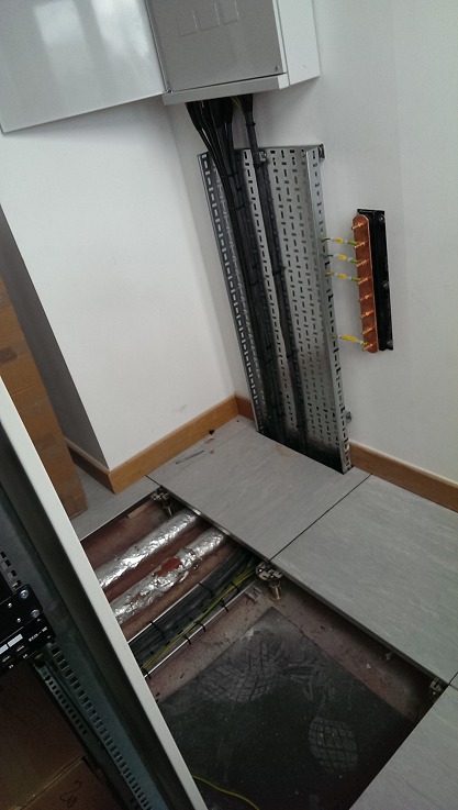
The cable tray to the OpenReach NTE is installed alongside the earth path. Every metallic element in the room (racks, trays, the DB enclosure) lands on the copper bar visible top-right of frame.
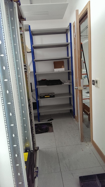
The store room runs on variable-height steel shelving with dado trunking presenting power and data points. The shelving is rated for distributed load, not point load, which constrains what we can put on it. That choice was made with one eye on the floor tile loadings underneath, the building isn’t a data centre and neither it nor the raised floor are spec’d to take a tonne of disk array stood on four feet.
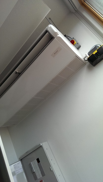
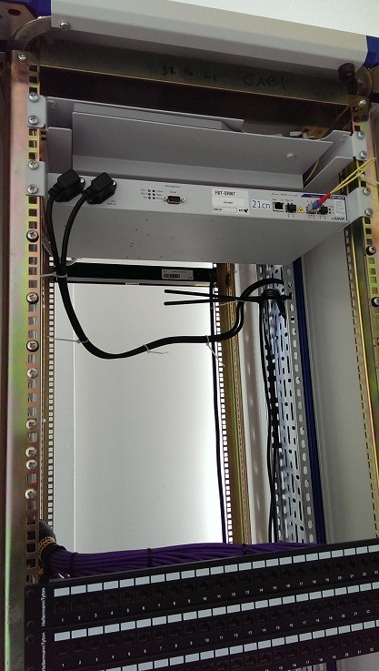
Air-conditioning is installed. A ceiling-cassette comfort unit rather than precision cooling, sized for the load three cabinets generate rather than the nine we left behind. It was originally going to drop in from the ceiling facing all three cabinets and blow cold air across the row, but there wasn’t enough room for the cassette in that position. It had to move to face cab 1, mounted above the power box and the earth bar, which leaves the final configuration a bit janky.
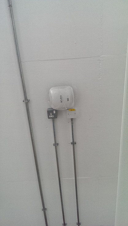
One of three Aruba wireless units is ceiling-mounted. Each Aruba is complemented by a power and data point. The Arubas are PoE, but the 13A socket leaves us room to fit something non-PoE later, if we ever want to.
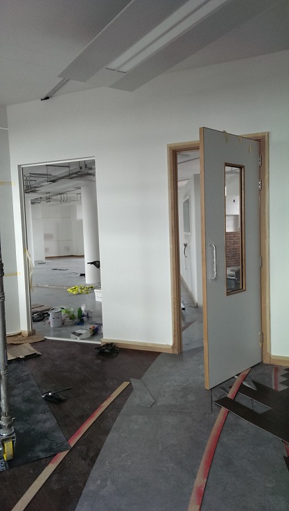
The open-plan floor space is being finished in parallel, which means dust, scaffold towers, and shared corridors right up until handover.
Part 3: ← Passive infrastructure and the carrier handoff · Part 5: Live, patched, and moved in →