Building a Server Room, Part 3: Passive Infrastructure and the Carrier Handoff
This is the third in a series of five posts documenting the planning, architecture, and build of a new server room under various building and budgetary constraints.
- Part 1 — Nine Cabinets into Three
- Part 2 — Fibre, Floor, and First Frames
- Part 3 — Passive Infrastructure and the Carrier Handoff
- Part 4 — Power, Cooling, and Connectivity
- Part 5 — Live, Patched, and Moved In
Three weeks on from part 2 (18 August 2014). The cabinets are in position, the cabling contractor is on site, and the BT engineers have been back to light the circuit. This is the post where the room starts to look like a comms room.
Small confession before we go on: in part 2, I had cab 1 pegged as the comms cab, but of course that didn’t survive contact with reality, because the miniscule clearance under the raised floor (the bloody pipes, again) forced all the access runs from the floor boxes to enter the room on the right-hand side (you can see the route in the matting photo in part 2) to hit cab 3 before anything else. Dragging that lot back across the room just to land it on the “first” cabinet would have been daft, so Cab 1 and Cab 3 have swapped roles. Cab 3 is now the patching and comms cab.
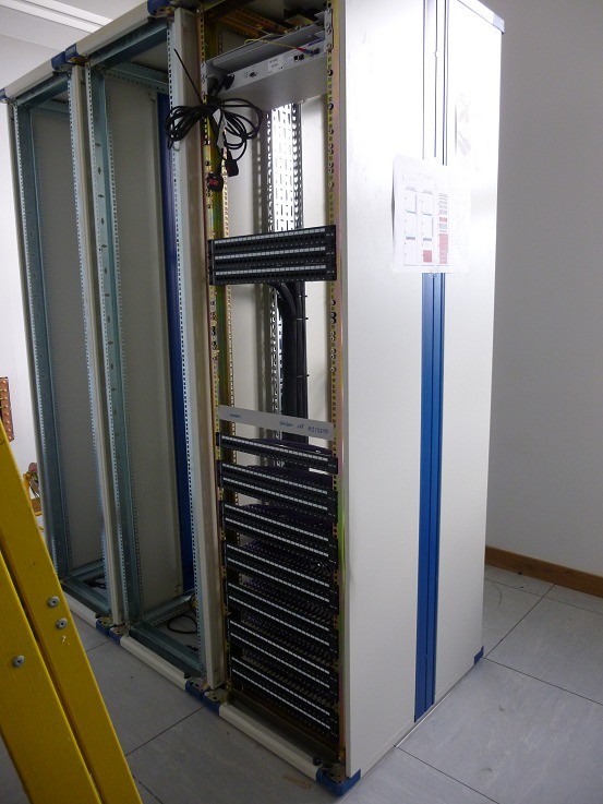
Patch panels are installed in cab 3, the comms cab. A little under 312 patch panel ports comprise the access port trunking to floor boxes around the office, with a further 72 patch panel points further up in cab 3 patching across to cabinets one and two, and to the dado for the steel shelves.
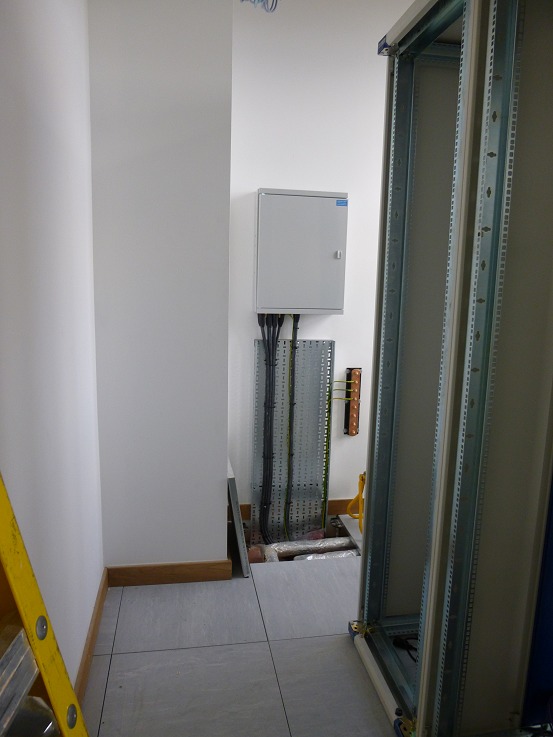
The power distribution board is mounted on the far wall, and each cabinet is earthed back to the copper bar visible to the right of it. Seven power lines emerge from the DB: two 32 amp (UPS and dado trunking) and five 16 amp (a single 16 amp to cab 3, and two 16 amp feeds each to cabinets one and two).
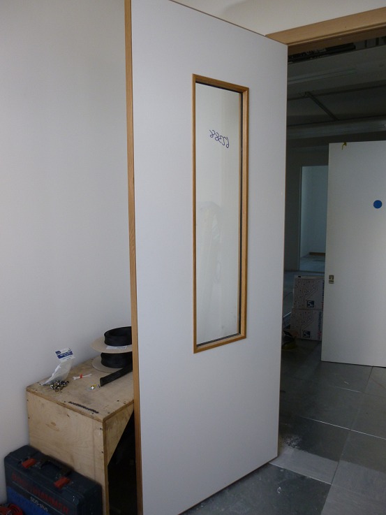
The comms room door is acoustically sealed. The narrow viewing panel lets you see whether anyone is inside before you punch in the code, and lets you see the front of cab 3 from outside the room.
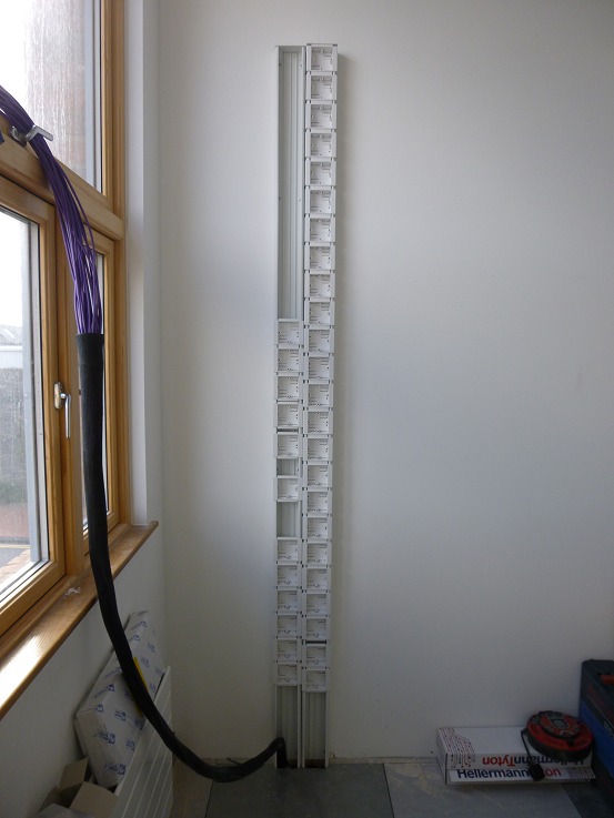
A first look at the power and data dado trunking as it is built. This runs at low level along the wall behind the steel shelving units, presenting 13A sockets and Cat5e outlets at workable heights for equipment that doesn’t justify a 19” cabinet.
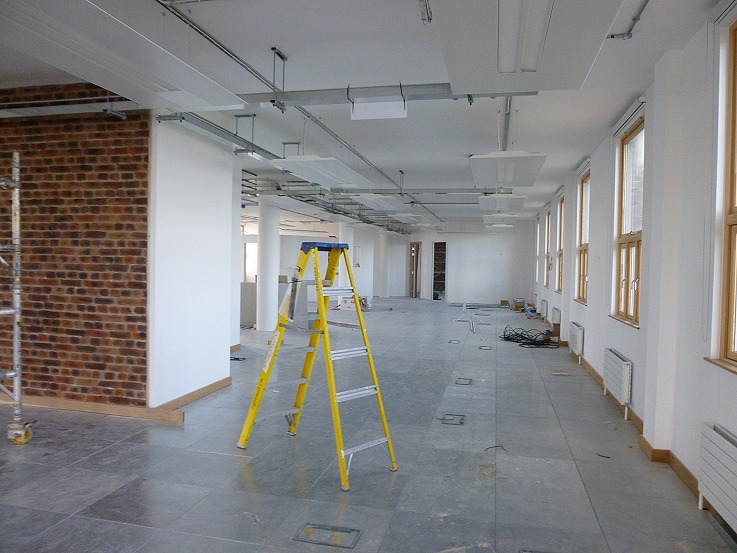
Brick cladding is fitted as a feature around the open-plan floor space. The comms room is white-walled and functional, but the rest of the space gets to have some character.
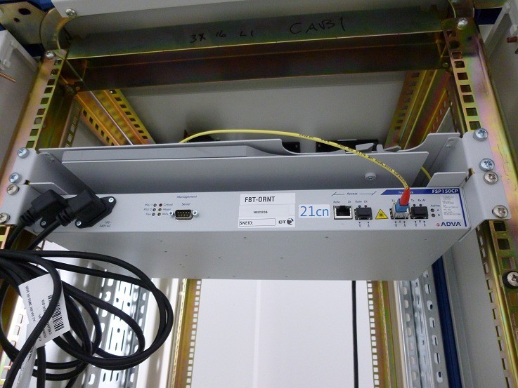
The fibre tray is installed and so is the BT OpenReach NTE. A 100Mbit circuit is run in on a 100Mbit bearer: a Virgin Media line delivered on a BT tail. The line presents Provider-Independent (PI) IP space, advertising via BGP a route to a /21 network (2048 IP addresses).
Part 2: ← Fibre, floor, and first frames · Part 4: Power, cooling, and connectivity →